TB400 SeriesTB400-TH
Unit Type
I/O Adapter
Signal Switcher / Distributor


Improving the troublesome connector unplugging and plugging operations involved in parallel running, leading to a significant reduction in man-hours.
*1 Products are warranted for years from the date of shipment.
| Warranty Period *1 | 3Years |
|---|---|
| Standard Lead Time | Custom Products |
| Power Supply | 24V DC |
| Connection | MIL connector (OMRON: XG4A-2034) |
Improving the troublesome connector unplugging and plugging operations involved in parallel running, leading to a significant reduction in man-hours.
*1 Products are warranted for year from the date of shipment.
| Warranty Period *1 | 3Years |
|---|---|
| Standard Lead Time | Custom Products |
| Power Supply | 24V DC |
| Connection | MIL connector (OMRON: XG4A-2034) |
| DO signal | : 16 ch/card × 2; total 32 ch |
| RO (relay output signal) | : 8 ch/card × 2; total 16 ch |
| AO (analog output signal) | : 16 ch/card × 2; total 32 ch |
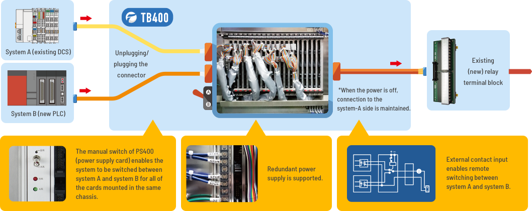
The unit is designed such that the system switches to system-A side whenever the power is off. Keeping the existing system connected to the system-A side for parallel running allows production to be continued without unplugging and plugging the connector. (After the completion of parallel running, the new system connected to system-B side must be reconnected to the system-A side.)

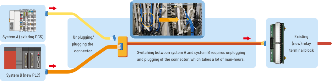
Parallel running of existing and new systems involves manual unplugging and plugging of the connector for every switching, requiring a lot of man-hours and therefore hindering efficient work.

When you install the TB400, you can easily switch signals without unplugging and plugging the connectors.
The connecting cables are flat, so you can do wiring work efficiently.

You can switch signals not only by the switch but remotely with external contact input. Therefore, you can perform your work more efficiently.
| DO signal | : 16 ch/card × 2; total 32 ch |
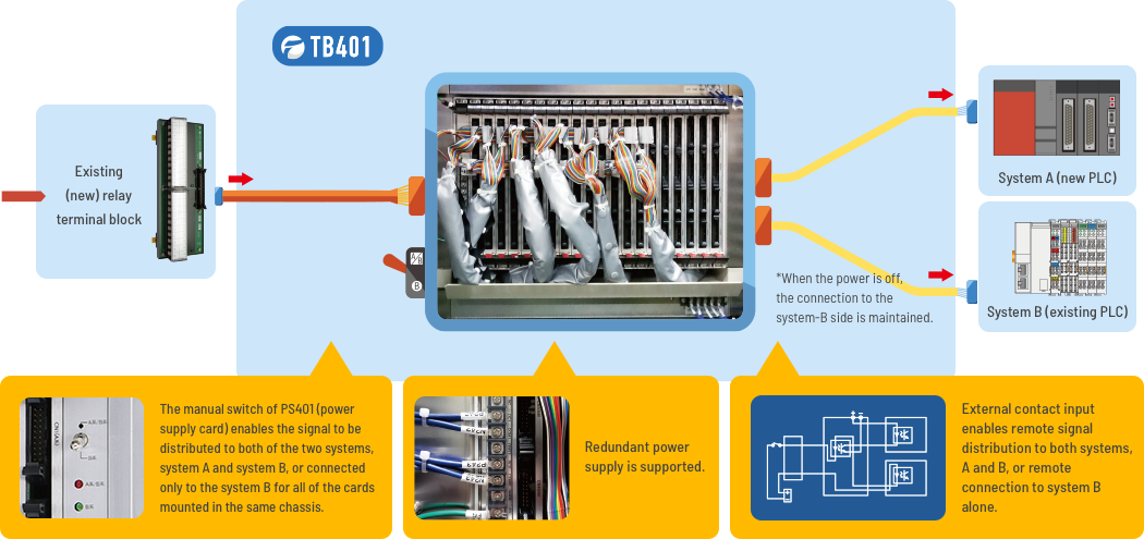
Mounting a non-conditioning I/O adapter (optional) "TH401-□" on the PCB inside the card allows connection to system A to be maintained even when system B (existing) is disconnected after parallel running (assuming that the PLC (DCS) should be connected only to system A).
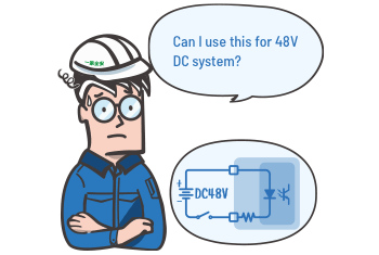
The TB401 also supports 48V DC DI signal.
Since the voltage to the output (PLC) side is always 24V DC, you can use the existing 48V DC sensor without any change.
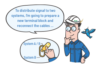
You don't have to prepare a new terminal block.
You can use the existing one as it is. When you connect it to the TB401, the unit will distribute signal to two systems, system A and system B.

You can switch signals not only by the switch but remotely with external contact input.
Therefore, you can perform your work more efficiently.
| Number of outputs | DO: 32 RO: 16 |
|---|---|
| Rated load of contact | 24V DC, 1A |
| Maximum load of contact | 48V DC, 0.6A |
| Signal wiring | MIL connector (OMRON: XG4A-2034) |
| Wiring method for common | One common ground line per 16 channels, 1.6A max. (for DO) |
| Power supply for relay activation | 24V DC ± 10%, supplied via RC400 backplane |
| Current consumption | 150 mA max. |
| Rated current of fuse | 1A |
| Insulation Resistance | Between each signal line and power line for relay activation: 100MΩ min. (@500V DC) |
| Withstand strength | Between each signal line and power line for relay activation: 1000V AC for 1 min. (cutoff current: 0.5mA) |
| Number of inputs | 32 |
|---|---|
| Maximum input voltage (system B) | 48V DC +10% |
| Maximum input current (system B) | 10mA |
| Signal wiring | MIL connector (OMRON: XG4A-2034) |
| Wiring method for common | One common ground line per 16 channels, 160mA max. |
| Rated output voltage (system A) | 24V DC ±10% |
| Rated output current (system A) | 6mA |
| Response time | 5usec max. |
| Power supply | 24V DC ± 10%, supplied via RC400 backplane |
| Current consumption | 200mA max. |
| Rated current of fuse | 1A |
| Insulation Resistance | Input (H / L) / system B-A / power: 100MΩ min. (@500V DC) |
| Withstand strength | Input (H / L) / system B-A / power: 1000V AC for 1 min. (cutoff current: 0.5mA) |
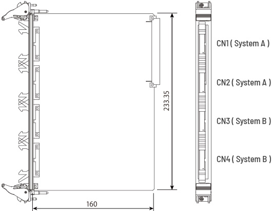
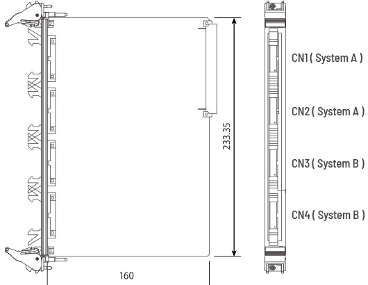
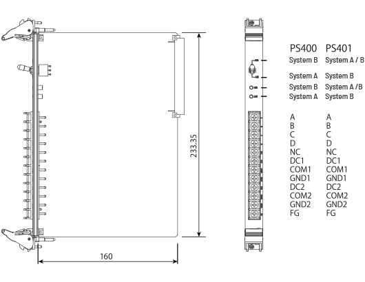
| Signal selector switch | PS400 (For TB400: DO) |
|---|---|
| (Toggle switch) | System-A side: Green LED ON, relay not activated (system A for signal) System-B side: Red LED ON, relay not activated (system B for signal) PS401 (For TB401: DI) System-A/B side: Red LED ON, photocoupler power ON (system A and system B for signal) System-B side: Green LED ON, photocoupler power OFF (system B for signal) 24V DC ±10%, redundant |
| Power Supply | Terminals A&B (#1): 24V / 10mA; contact input terminals C&D (#3): Contact output |
| External contact signal | Front-panel M3.5 screw |
| Wiring | PS400 3A: TB400-20ch, with selector switch at system-B side |
| Maximum current consumption | PS401 4A: TB401-20ch, with selector switch at system-A/B side |
| Rated current of fuse | 5A |
| Insulation Resistance | Power and external cantact terminal to F.G.: 100MΩ min. (@500V DC) |
| Withstand strength | Power and external contact terminal to F.G.: 1000V AC for 1 min. (cutoff current: 5mA) |
| Operating environment | Temperature: 0 to 55℃; Humidity: 5 to 95% RH (non-condensing) |
|---|---|
| Storage temperature | 0 to 55℃ |
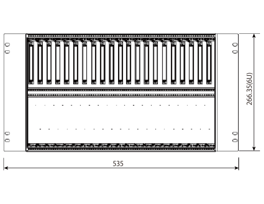
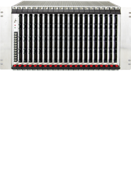
| Installation | Mounted in 19-inch rack, RC400 |
| External dimensions | 6U4HP (for details, refer to outline drawing) |
| Weight | 370g max. |
| Front panel | Aluminium |
| PCB | Double-sided board made from glass fabric, epoxy resin (FR-4:UL 94V-0) |
| Conformal Coating | Humiseal 1A27NSLU (Polyurethane) * This will be optional at extra cost, starting with orders placed on November 1, 2022. |
| Number of units mountable per rack | TB400 or TB401: 20, PS400 or PS401: 1 (left) |
|---|---|
| Operating environment | Temperature: 0 to 55℃; Humidity: 5 to 95% RH (non-condensing) |
| Storage temperature | 0 to 55℃ |
| Installation | Rack mounting |
| External dimensions | 6U, 19 inch (for details, refer to outline drawing) |
| Weight | 4.5kg max. |
| Housing | Aluminium |
| PCB | Glass fabric epoxy resin |
| Conformal Coating | Humiseal 1A27NSLU (Polyurethane) * This will be optional at extra cost, starting with orders placed on November 1, 2022. |
| Power Supply | 24V DC ±15%, 0.6A typ. |
|---|---|
| Wiring | Front-panel M4 screw |
| Alarm signal output | Open collector: 27.6V DC max., 5mA max. |
| Operating environment | Temperature: 0 to 55℃; Humidity: 5 to 95% RH (non-condensing) |
| Storage temperature | 0 to 55℃ |
| Installation | Rack mounting |
| External dimensions | 1U, 19 inch (for details, refer to outline drawing) |
| Weight | 2.5kg max. |
| Housing | Aluminium |